



 Home /
 How to Size a Valve Actuator: Torque Calculation & Safety Factor
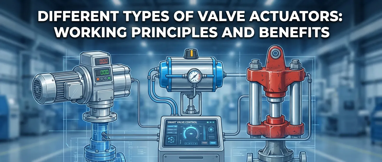
Different Types of Valve Actuators Working Principles and Benefits
Nov 29, 2025
Durable Anti-Corrosion Valves and Actuators for Desalination Plants
Jan 12, 2026

Ball Valve Maintenance Guide Preventive Routine Procedures 2026
Nov 29, 2025

Actuated Valve Guide: Working Principle, Types & Selection
Dec 31, 2025
We build actuators at DELCO, and roughly one in five sizing requests that lands in our inbox is wrong. Not by a little. Someone picked a running-torque number from a valve datasheet, multiplied it by 1.25, and ordered. Then the actuator stalls on the first cold morning with the valve bone-dry of lubricant and 16 bar sitting across the seat.
The good news: sizing an actuator is a seven-step process, and every step is mechanical once you know the order. This guide walks through it with worked numbers, the safety factors we actually use on production orders, and the mistakes we catch before they ship.
Quick Answer
Size the actuator by multiplying the valve's highest torque demand — usually breakaway or seating torque, at worst-case pressure and temperature — by a safety factor of 1.25–1.5 (up to 2.0 for dirty or safety-shutdown service). Then select an actuator whose output exceeds that figure at minimum supply pressure. For spring-return units, verify the spring stroke too, not just the air stroke.
What You Need Before You Start
Four inputs, no exceptions:
- The valve's torque data from the manufacturer — breakaway, running, and seating torque at a stated differential pressure
- Your worst-case operating conditions — maximum differential pressure, media temperature, seat material
- The actuation spec — electric or pneumatic, supply pressure or voltage, fail-safe direction if any
- The valve's maximum allowable stem torque and ISO 5211 mounting dimensions (printed on the valve datasheet or its manufacturer's interface standard)
If item 1 is missing, the valve manufacturer quoting torque "on request" is a red flag in itself. Estimation formulas exist (we'll show one), but they belong in the proposal stage, never the purchase order.
Step 1: Get the Valve's Three Torque Numbers
A quarter-turn valve doesn't have one torque. It has a torque curve, and three points on that curve decide everything:
| Torque Type | What It Is | Ball Valve | Butterfly Valve |
|---|---|---|---|
| Breakaway | Torque to unseat from closed | Governs (highest) | Governs for resilient seats |
| Running | Torque mid-travel | 40–60% of breakaway | Lower; seat contact through stroke |
| Seating / end | Torque to close tight against the seat | Slightly under breakaway | High on resilient seats |
| Dynamic | Fluid force on the disc/ball mid-travel | Minor on most ball valves | Peaks around 60–80% open |
Breakaway is where sizing fails. On a floating-ball valve with PTFE seats, the ball presses into the seat under line pressure while the valve sits closed; the seat material cold-flows into the ball's surface finish. Leave that valve closed for six months and the breakaway torque you measure on day 180 can run 20–30% above the datasheet. We've seen it on water treatment isolation valves that never cycle.
No datasheet? For proposal-stage estimates on a PTFE-seated floating ball valve, a rough seat-friction estimate is:
T_break ≈ K × d² × ΔP, with K ≈ 0.03–0.06 for PTFE, d = bore in mm, ΔP in bar — then sanity-check the result against published torque tables for the same size and class. If your estimate lands far from the tables, the estimate is wrong. (While theoretical friction equations provide quick proposal-stage estimates, factory torque tables under differential pressure always take precedence—formulas rarely capture seat deformation under real line pressure.)
Step 2: Set Your Worst-Case Conditions
Torque numbers are meaningless without the conditions attached. Datasheets publish torque at a stated differential pressure; your job is to size for the pressure the valve will actually see, not the one it usually sees.
Four condition checks, in order of how often they're skipped:
- Maximum ΔP, not nominal. A pump dead-heads eventually. Size to that number.
- Temperature. PTFE seat friction climbs with temperature; above 200°C you're on metal seats anyway with their own friction profile. Add margin.
- Media. Scale-forming water, slurry tailings, or crystallizing product will weld the seat to the ball over time. This moves you up a safety-factor tier.
- Time between cycles. A valve that strokes hourly behaves differently from one that sits closed for a season. Dormant ESD valves are the classic trap: first demand on the torque comes after years without movement.
Step 3: Pick the Governing Torque
Line up the numbers at your worst-case conditions and take the highest:
- Ball valves: breakaway usually governs; seating runs a close second
- Resilient-seated butterfly valves: breakaway and seating govern; check dynamic torque if the valve throttles at high velocity
- Triple-offset butterfly valves: breakaway runs 2–3× running torque, thanks to the cam-action seat
Write the governing number down with its units. N·m, not "about a hundred." It goes into everything downstream.
Step 4: Apply the Safety Factor
Now the margin. A safety factor exists because torque data has manufacturing tolerance (±15–20% between identical valves is normal), supply pressure wanders, packing tightens over years, and seats age. This is the table we work from:
| Service | Safety Factor | Why |
|---|---|---|
| Clean service, on/off, moderate cycling | 1.25–1.5 | Covers tolerance + wear |
| Dirty, scaling, or corrosive media | 1.5–2.0 | Seat deposits, corrosion friction |
| ESD / safety shutdown | 1.5–2.0 | Must move after long dormancy |
| High temperature (>200°C) | 1.5–2.5 | Thermal expansion, seat friction rise |
We used to quote 1.25 across the board on clean water work. Then a food-plant client ran a dosing line that crystallized at every weekend shutdown, and three actuators in a row tripped their torque switches on Monday startup. Their "clean service" was clean four days out of seven. Service factor 1.5 went on the reorder, and the failures stopped. The lesson: the factor follows the worst day, not the average day.
Step 5: Size the Actuator — at Minimum Supply Pressure
Here's where pneumatic and electric sizing diverge.
Pneumatic. Manufacturers publish torque output versus supply pressure. Size against the minimum supply pressure your plant guarantees, not the nominal. An actuator that delivers 150 N·m at 6 bar may deliver barely 110 N·m at the 4.5 bar your compressor dips to during peak demand. That dip is when the valve decides not to open. For double-acting units, this single check covers you.
Spring-return. Now check both strokes separately. The air stroke opens the valve (or closes it, per your fail direction); the spring stroke drives it back on air failure. Spring torque falls as the spring extends, so the number that matters is the spring's torque at the end of its stroke — the last 10% of travel, where seating torque peaks. An actuator that closes the valve crisply on air but drifts to a stop at 80% closed on spring power alone has failed its sizing, quietly, in a way nobody notices until the power event.
Step 6: Check the Valve Can Survive the Actuator
Undersizing gets all the attention. Oversizing damages valves just as dead — it just takes longer.
Every valve has a Maximum Allowable Stem Torque (MAST) limit. Over-torquing can permanently twist the stem or shear the drive key. Bolt a double-acting actuator capable of 500 N·m onto a valve whose stem fails at 300, and the first full-pressure stroke under a jammed seat twists the stem or cracks the housing. The check is one division: actuator maximum output must stay under the valve's allowable stem torque.
The ISO 5211 mounting interface ties into this. The flange (F03 through F25) and drive square sizes roughly track torque ranges — F05 around 30–80 N·m, F07 around 80–200 N·m, F10 around 200–500 N·m — so an actuator that wildly over-runs its flange class is a sign the pairing was never checked. When in doubt, ask the valve maker for the allowed torque at the valve interface. Reputable ones publish it; Emerson's actuation datasheets, for instance, walk the same max-stem-torque check.
Step 7: Adjust for Electric Duty Cycles
Electric actuators need one more pass:
- On/off service (duty S2): size on rated torque at your voltage tolerance. Straightforward.
- Modulating service (duty S4/S6): the motor reverses constantly and heat builds. Derate output to 70–90% of the on/off rating — check the manufacturer's duty-cycle table — and confirm the unit is actually a modulating model with the control board and duty cycle to match. A regular on/off actuator on a 4–20 mA loop will cook itself inside a quarter.
- Torque switches: set above your worst-case required torque but below the valve's allowable stem torque. That window is the whole game on high-pressure ball valves.
(S2 = On/Off open-close service; S4 = Continuous modulating/positioning service).
Two Worked Examples
Example 1: Electric Actuator + Ball Valve (On/Off Duty)
- Design Basis: DN100 (4-inch) Floating Ball Valve • PTFE Seats • Clean Water • 16 bar Max ΔP
- Raw Torque Data: Breakaway: 95 N·m • Running: 55 N·m • Seating: 90 N·m
- Governing Torque: 95 N·m (Breakaway governs)
- Selected Safety Factor: 1.3 (Infrequent cycling service)
- Target Output Required: 95 N·m × 1.3 = 123.5 N·m
- Actuator Selection: Select a 150 N·m quarter-turn electric actuator with an ISO 5211 F07 mounting flange.
- MAST Safety Verification: Confirm the actuator's stall/maximum torque output remains below the valve's Maximum Allowable Stem Torque (MAST, typically ≈ 200 N·m for this class).
Example 2: Pneumatic Spring-Return Actuator + Butterfly Valve (Fail-Safe Duty)
- Design Basis: DN150 (6-inch) Concentric Butterfly Valve • EPDM Seat • Water Service • 10 bar ΔP • Fail-Close Required
- Raw Torque Data: Breakaway: 70 N·m • Seating: 65 N·m • Dynamic Peak: 48 N·m
- Governing Torque: 70 N·m (Breakaway governs)
- Selected Safety Factor: 1.25 (Clean water, frequent cycling)
- Target Output Required: 70 N·m × 1.25 = 87.5 N·m
- Operating Constraints: Minimum guaranteed plant air supply: 5 bar
- Actuator Selection: Select the smallest spring-return model whose published torque table at 5 bar exceeds 88 N·m at both the end of the air stroke and the end of the spring stroke.
- Critical Check: Always verify the torque curve at full spring extension—the end-of-stroke spring torque is the exact force that closes your valve tight during a plant air failure.
Common Sizing Mistakes (We See These in Inquiries)
- Sizing on running torque. The actuator spins the valve happily at mid-stroke and stalls at the seat. Every time.
- Forgetting the minimum supply pressure. Works at commissioning with a fresh compressor, stalls two years later.
- Checking only the air stroke on spring-return units. The fail-close function nobody tested is the one that runs the plant incident report.
- Oversizing "to be safe" without the stem-torque check. The actuator doesn't stall; it breaks the valve instead.
- Modulating duty on an on/off actuator. Derating isn't optional on S4 duty. The motor doesn't care what the brochure promised.
- Using nominal pressure instead of maximum. Dead-head pressure exists. Size for it.
From the Field
Three habits we've built after years of quoting valve-plus-actuator packages:
- Ask how long the valve sits closed. The answer moves the safety factor more than any datasheet revision.
- Quote the package, not the actuator. When the same supplier provides valve and actuator, the stem-torque check and the torque-switch window are one department's problem instead of two vendors' finger-pointing.
- Keep the sizing sheet with the order. When the actuator trips its torque switch in year five, the first question is "what was the design margin?" If nobody knows, you re-derive the whole sizing from scratch.
FAQ
What safety factor should I use for a valve actuator? 1.25–1.5 for clean on/off service; 1.5–2.0 for dirty media, high temperature, or ESD duty; up to 2.5 for extreme combinations. The factor should cover your worst operating day, including valve aging, not the commissioning day.
What is breakaway torque on a valve? The torque needed to move the closure element off its seat from the fully closed (or open) position. For ball valves it's usually the highest torque of the stroke, and it grows with seat dwell time and differential pressure.
Can an actuator be too powerful for a valve? Yes. If the actuator's maximum output exceeds the valve's allowable stem torque, a jammed seat or foreign object lets the actuator twist the stem or crack the valve body. Always check actuator max output against the valve's stem limit.
How does supply pressure affect pneumatic actuator sizing? Output torque scales with supply pressure. Size against the minimum guaranteed plant air pressure, not nominal — and for spring-return actuators, verify the spring side meets torque requirements independently of air.
Do electric actuators need a safety factor too? Yes, same logic: seats age, packing tightens, tolerances stack. Apply the same 1.25–1.5 multiplier, and derate the actuator output for modulating (S4) duty rather than on/off duty.
Where do I find a valve's torque data? The valve manufacturer's datasheet or torque table, published at stated differential pressures and seat materials. If it isn't published, request it before ordering the actuator — estimate only for proposals, never for purchase orders.
Unsure about your worst-case torque or MAST limits?
Submit your pipeline conditions [here]. DELCO’s application engineering team will review your specifications, consult with you on operating margins, and deliver a tailored Actuator Sizing Verification Sheet aligned with your project schedule.
Share on Social:


Contact Us
In This Article
Different Types of Valve Actuators Working Principles and Benefits
Nov 29, 2025
Durable Anti-Corrosion Valves and Actuators for Desalination Plants
Jan 12, 2026
Ball Valve Maintenance Guide Preventive Routine Procedures 2026
Nov 29, 2025
Actuated Valve Guide: Working Principle, Types & Selection
Dec 31, 2025